FAQ
Q: How does the P3 monitor my transmit signal?
a. The Transmit Monitor feature will use the P3 display to present transmit power, modulation and SWR bar graph displays
b. Used in conjunction with an external RF sensor placed into the transmission line, the P3 samples the RF signal in order to process it.
c. When the K3 goes into transmit, the modulation envelope "oscilloscope" display temporarily replaces the spectrum display whenever the rig goes into transmit mode. This can be turned off when needed using the P3’s menu.
Q: When the K3 goes into transmit, what happens to the P3’s received-signal displays?
a. Only the spectrum display is over-written by the modulation envelope during transmit.
b. If you have only the spectrum display enabled, the entire screen will be overwritten with the modulation envelope.
c. If the waterfall display is enabled, the waterfall will freeze during transmit but the waterfall image is maintained as the modulation envelope is displayed in the spectrum portion of the display.
Q: I enjoy fast CW operation. How will the P3 display be updated if I am switching between Transmit and Receive so fast?
a. The P3 modulation monitor (and watt/SWR meters) uses a 400 mS delay to determine when to switch back from transmit to receive. So as long as the time between dits or whatever is less than this delay, you don't see the modulation display turning on and off.
Q: Will I be able to see the Transmit waveform on an SVGA monitor, too?
a. No. The transmit signal results will be on the main P3 display screen.
Q: Will the meter readings be shown in Time or Frequency domains?
a. Meter readings will display in the time domain. When transmitting, the spectrum display can be replaced by a display of the modulation envelope.
b. Unique to the P3, the envelope display can optionally be set up as a split screen where the left half shows the CW rise and the right half the fall so you can see both edges at the same time.
Q: How will the meter readings be presented on the P3 display for Phone/SSB modes?
a. The modulated signal envelope display takes the place of the ‘real-time’ window on the P3. The waterfall, however, will remain in place. The meters, seen below, begin measurements when the K3 enters Transmit, as does the upper waveform display. When enabled, the meters will remain on the screen.

You can also turn off the waveform envelope and monitor only the meters. In this mode, the bar graph meters will be active when you go into transmit.

Q: How will the meter readings be presented on the P3 display for CW modes?
a. Here is the display, shown in CW split window form, showing rise and fall time of a single element. That is, split windows are available when the K3 is in CW mode only.

The display can also be set up to display a longer scale and monitoring high-speed CW elements (~ 50 wpm).

Q: How will the operator be able to control the displays?
a. Both the modulation envelope and meter displays can be enabled and disabled via menu entries.
b. You can also change the full-scale power for the meter and the millisecond/div setting for the modulation envelope display. The modulation envelope display is auto-scaled when required.
c. The amplitude of the power meter and digital power readout can be calibrated in a menu setting (MtrScale).
Q: How much additional current will the Transmit Monitor option add?
a. When installed, the added current draw for the Transmit Monitor is expected to be less than 10 mA—a very small fraction of the P3’s total current drain.
Q: If my K3 is configured with the 2M option, can I monitor VHF Transmit waveforms with the P3 Transmit Monitor option?
a. Yes. You can select the Sensor that works at VHF frequencies to do so.
Q: What is the Transmit monitor option and what is it used for?
a. In addition to the many features for Receive operations, operators now can outfit their P3 to include a Transmit waveform monitor.
b. This means that the P3’s display will provide TX monitoring when the K3 goes into transmit.
Q: To get the full kit of parts, what do I need to order?
a. All P3s will require an adapter board to which a sensor will be connected.
b. You will then choose the proper sensor based on band and power level.
| I want to Monitor |
Items needed for your order |
| 160M to 6M at less than 200 watts |
- TX Monitor option
- 200 watt HF sensor module
|
| 160M to 6M at less than 2000 watts |
- TX Monitor option
- 2kW HF sensor module
|
| VHF (2 meters) at less than 200 watts |
- TX Monitor option
- VHF sensor
|
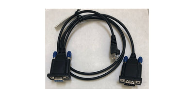
** Note: The interconnect cable will be included in the product order
Q: What is involved with installing them in the P3?
a. There will be a small adapter board to install inside your P3. It will fill one of the unused holes on the P3 back panel, labeled SENSOR.

b. For signal pickup, there will be an external power sensor similar in size and form to the W2 wattmeter sensor.

c. These 2 items will be connected with CAT5/CAT6 cable plugging into RJ45 jacks. A length of cable will be provided as part of the product purchase.
Q: Can I connect more than one sensor at a time to the P3?
a. No. One sensor can be connected at a time. Choose the most important bands to monitor for your needs.
b. You can, however, order more than one sensor and then connect them individually as needed.
Q: Can I connect more than one sensor at a time to the P3?
a. No. One sensor can be connected at a time. Choose the most important bands to monitor for your needs.
b. You can, however, order more than one sensor and then connect them individually as needed.
Q: What is the maximum length of the interconnecting cable I can use?
a. The Sensor interconnect wire shipped with the option is 168 cm (about 5 ft, 6 inches) long. It will have RJ45 connectors on each end. To ensure guaranteed operation, this is the supported length.
b. Operators are welcome to extend the length of the interconnect cables, if needed, but Elecraft recommends positioning the Sensor in such a way that interconnect cable lengths are minimized.
Q: When I install the Sensor, is there an optimum place on my transmission coax that it needs to be placed?
a. This will depend upon what you want to measure. Here are 2 applications:
b. Placement on output side of a tuner: This will allow you to monitor the operation of the entire transmission line and antenna system as a whole.
c. Placement where the antenna joins the transmission line: This will allow you to monitor the optimum operation of the antenna. This enables you to monitor and adjust antennas with adjustable resonance points (SteppIr, for example) for maximum power transfer to the antenna itself.
Q: Do I need to have the SVGA option installed to use the TX Monitor?
a. No. You do not need to have the SVGA option installed first. The Transmit Monitor option can be installed at any time on any P3 that has been produced to date.
Q: What is installed in the P3 itself?
a. There will be a small board added to the P3’s Input/Output (I/O) board. The rear panel is already punched with a hole labeled SENSOR where it will appear when reassembled.


b. As with all Elecraft options, this addition will not require any soldering for installation.
Q: Will I need to update my P3 firmware to use the Transmit Monitor?
a. Yes, there will be a firmware release to support the new hardware.
Q: Are there any firmware updates or menu changes required for my K3 to use the Transmit Monitor option?
a. No. The K3’s firmware or configurations are not affected by the Transmit Monitor option installation.
Q: I have a P3 but it is connected to a different radio than the K3. Will I be able to use the Transmit Monitor option in my shack?
a. Unfortunately, the Transmit Monitor option will not operate with non-Elecraft K3 radios. This is due to the P3 having no way of knowing when the transceiver has gone into transmit.
Q: I am running a legal limit linear amplifier with my K3/P3 combo. What is the highest power I can use with the P3 Transmit Monitor?
a. When you order the P3 Transmit Monitor option, there will be a version available for a 2 KW sensor. This will allow you to use a legal limit linear amplifier ahead of the sensor.
b. This sensor will be rated for a maximum of 2,000 watts in all modes.
Q: I would like to use the P3 Transmit Monitor for QRP systems. How can this be implemented?
a. The 200 watt sensor can be used to monitor transmission envelope down to as low as 2 watt full-scale display. This will provide reasonably accurate waveform displays down to a few tenths of a watt.
b. Likewise, the 2Kw sensor can be used as low as a 20 watt scale.
c. We do recommend the 200 watt sensor for QRP projects where possible.